Most construction problems do not start on site. They start on paper. When drawings are unclear, dimensions are misunderstood, or layouts are imagined differently by each stakeholder, the project pays for it later.
This is where professional 2D/3D Rendering Services stop confusion before it becomes cost. At Construction Cost Estimation Service (C.C.E), we use 2D and 3D rendering as a practical construction tool. Our renderings are not made just to “look good.” They are made to help owners, contractors, and estimators clearly see what will be built, how it fits, and where money can be saved before construction starts.
To give you a clear, measurable quantity breakdown that protects your bid, your budget, and your reputation.
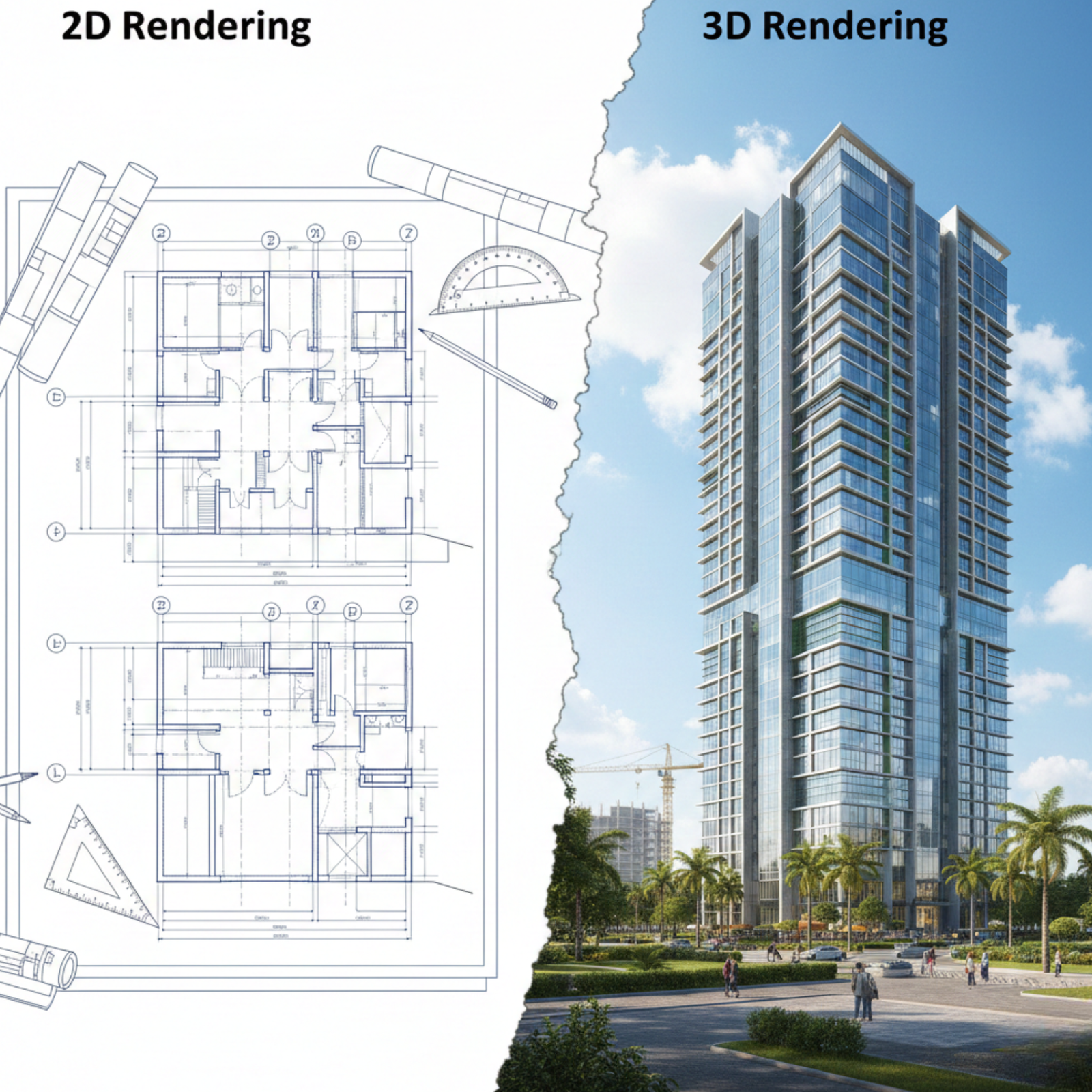
Construction drawings explain intent. Renderings explain reality. A 2D plan shows lines. A 3D rendering shows space, scale, and relationships. When clients ask for 3d visualization to see if things fit my room, what they really want is certainty.
They want to know if furniture blocks circulation, if ceiling heights feel right, and if finishes clash before spending money. Our 3d rendering services support accurate estimating, better approvals, and fewer site changes.
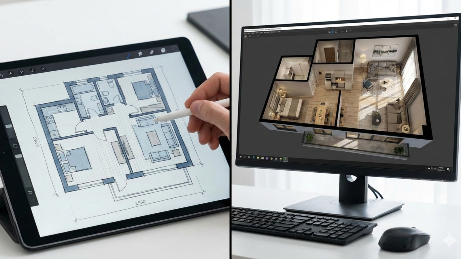
2D rendering is not outdated. It is the backbone of measurement and takeoffs. We prepare clean, scaled drawings that estimators and contractors can rely on. This includes plans, elevations, and details created or refined from existing files.
Many clients ask how to render in AutoCAD 2D or how to render a 2D plan in AutoCAD. Our team already works inside these environments, producing drawings that align with estimating workflows instead of decorative visuals.

3D rendering removes guesswork. A 3d rendering of a house allows owners to approve layouts faster. A 3d architectural rendering helps developers present projects to investors. Contractors use 3d floor plans to explain scope clearly to trades.
Whether it is interior space planning or full 3d rendering architecture, the goal is always the same: fewer assumptions and clearer communication.
Clients often ask about tools because they search for the best free 3d modeling software or a free 3d model design software. While free tools can help beginners, professional construction rendering requires precision, control, and compatibility.
We work with industry-standard platforms including 3D 3ds Max, AutoCAD, and other professional 3d architecture software. These tools allow us to deliver files that integrate with estimating, drafting, and construction documentation.
Choosing between 2D and 3D is not about preference. It depends on what decision needs to be made.
Rendering Type | Best Used For | Why It Helps |
2D Rendering | Plans, sections, takeoffs | Accurate measurements |
3D Rendering | Visual approval, coordination | Reduces design errors |
3D Floor Plans | Space planning | Clear layout understanding |
Architectural 3D Rendering | Client presentations | Faster approvals |
Most projects benefit from using both together instead of choosing one.
Interior spaces create the most questions. Clients often search for design room 3d or 3d interior design software because it is hard to imagine scale from drawings alone. Our renderings show furniture placement, clearances, finishes, and lighting in context.
This is especially useful when owners want to test layouts or when contractors need confirmation before ordering materials.
Exterior massing and façade design affect approvals and budgets. Our architectural 3d rendering services present buildings realistically without over-stylization. We focus on proportion, materials, and constructability rather than marketing gloss. This approach supports planning approvals, stakeholder presentations, and accurate scope understanding.
Rendering is not separate from estimating. It supports it. Clear visuals help estimators understand scope faster. When paired with construction cost estimation services, renderings reduce assumptions and rework.
This is especially helpful when reviewing complex geometry, mixed materials, or custom designs that are difficult to read in flat drawings.
Clients often ask technical questions such as how to render 2d art, how to render a 2d drawing in AutoCAD, or how to render 2d animation in Blender. Our role is not to teach software tutorials but to deliver results that support construction decisions. We focus on outputs that builders and owners actually use.
Rendering works best when drawings are clean. We often coordinate rendering with Plans/Blueprints Drafting Services . This ensures the rendered model matches the approved drawings, avoiding conflicts between visuals and construction documents.
Our clients include homeowners planning renovations, contractors bidding projects, and developers preparing approvals. Homeowners want clarity. Contractors want accuracy. Developers want confidence. Rendering supports all three when done correctly.
Rendering saves money when it prevents mistakes. A layout change made in 3D costs nothing. The same change made after framing costs real money. That is why rendering is not an expense. It is a preventive tool.
Project Type | Rendering Purpose | Value |
Residential Homes | Room layouts | Avoids rework |
Commercial Spaces | Tenant layouts | Faster approvals |
Multi-Family | Unit repetition | Consistent design |
Renovations | Before/after clarity | Reduced surprises |
2D/3D Rendering Services create visual representations of construction designs. 2D focuses on plans and elevations, while 3D shows realistic views of spaces and buildings.
3D rendering helps clients see scale, layout, and materials clearly. This reduces misunderstandings and design changes during construction.
They serve different purposes. 2D drawings are essential for measurements and permits. 3D rendering improves visualization and decision-making.
Yes. Clear visuals help estimators understand scope, reducing assumptions and errors in construction cost estimation services.
Yes. We use professional tools such as 3D 3ds Max and AutoCAD instead of relying on basic or free modeling software.
Yes. Homeowners use our services to visualize rooms, layouts, and renovations before committing to construction.
Yes. We provide interior room renderings, exterior building renderings, and full architectural 3D rendering.
Yes. We convert existing 2D drawings into accurate 3D models and renderings.
Most renderings are completed within a few days, depending on project complexity and revisions.
No. Renderings support drawings but do not replace construction documents required for permits and building.
OUR SERVICES
Contact us today to get started on your construction projects and experience the difference of working with Construct Estimates.
Get notified about new articles